Vane Physics
 
Contact Angle

The contact angle is the angle formed by the liquid surface in contact with a solid. A wetting liquid has a contact angle of <90 degrees and a non wetting fluid >90 degrees.

Because the geometry is truly three dimensional (not one or two dimensional as assumed in the equations on this page), it is possible that propellant will rise in a vane corner to a fixed height and stop if the contact angle is not zero. Fortunately, all propellants in current use have a contact angle of zero or near zero (<5 degrees) when in contact with titanium - the material used in the vast majority of PMDs. This ensures maximum performance with titanium.

When the contact angle is not zero, vanes can still be employed but greater care must be used in establishing the geometry. Simple vanes, perpendicular to the tank wall, may not be the best choice when the contact angle is large. With large contact angles the vane design is critical but large contact angles do not preclude the use of vanes.


Basics
 

Wetting liquids in low g will flow into the corners formed by solid PMD components. This allows liquid to "climb" up hill, against the hydrostatic force produced by the thruster acceleration. By properly designing the solid structure, sufficient flow area can be attained to meet the thruster demand flow rate.

The propellant illustrated in the figure to the left will flow up the incline against the hydrostatics only if the downstream radius is sufficiently smaller than the upstream radius. In the most basic terms, the surface driving pressure will be balanced by the dynamics, the viscous losses, and the hydrostatics. If the driving pressure is insufficient to overcome the opposing forces, flow up the incline will not occur. The simple force balance can be expressed as:

The steady flow equations can be derived from the continuity and momentum equations:

continuity:

a

momentum:

a

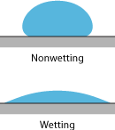
equation of state (surface tension):

a

Combining and reducing:

a

The governing steady flow equation has some interesting features.


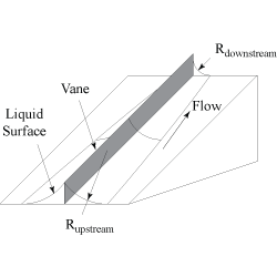
First, the radius of curvature along the length of the flow path is easily solved by simple integration.

Second, the denominator can go to zero indicating a choking phenomenon. This is similar to choking in supersonic flow except that the limiting velocity is not the density wave propagation speed but instead the area wave propagation speed.

The force balance equation and the steady flow equation found on this page do not fully characterize vane flow. The flow transients are critical to ensuring proper vane performance. The unsteady flow equations also can be derived from the continuity and momentum equations but the solution is not as straightforward. More details about unsteady flow can be found in the reference below.

For more information on the design, use, and physics of vane flow please see

AIAA 91-2172 Propellant Management Device Conceptual Design and Analysis: Vanes